MIL-PRF-62539A
SWITCH
A B
C D
ADJUSTABLE
VOLT-
11668620
REGULATED DC
V
METER
POWER SUPPLY
24 DC
CASE GROUND
24 V
LAMP
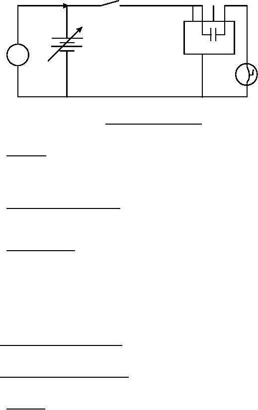
FIGURE 1. Schematic for voltage tests.
4.5.5 Time delay. The module shall be connected to 0-34 V dc variable voltage power
source per figure 3 with voltmeter and oscilloscope (or electronic counter). Preset power supply
voltage to 11.25 ± 0.25 V dc. Close switch, energizing module and initiating scope trace sweep.
When internal relay drops out, scope trace indicates time delay. See figure 3.
4.5.6 Starter switch bounce (figure 3). Apply 24 V dc with an initial simulated switch
bounce wave form of 6 ms duration to pin A of the module with the case grounded. Continuity
shall exist between pins B and D.
4.5.7 Dielectric strength . The assembly shall be tested as follows:
a. Connect pins A and C to the case (ground) (reference 3.4.4).
b. Apply 1000 V rms from pin B to case.
c. Apply 1000 V rms from pin D to case.
Verify that leakage of current through circuit insulation to ground is not greater than 100
milliamperes (mA).
4.6 Interface requirements verification. Interface requirements shall be verified using one
or more of the methods specified in 4.2.
4.7 Ownership and support verifications. Ownership and support verifications, except as
specified below, shall be verified using one or more of the methods specified in 4.2.
4.7.1 Endurance. After exposure to waterproofness test of 4.8.1, when connected into a
circuit as shown on figure 2, and 24 V dc are applied to pin A, the module shall be operated for
3000 cycles making at 100 A and breaking at 20 A at each of three ambient: -54°C (-65°F) +24°C
(+75°F), and +149°C (total of 9000 cycles). Verify that the module conforms to 3.5.1.
9
For Parts Inquires call Parts Hangar, Inc (727) 493-0744
© Copyright 2015 Integrated Publishing, Inc.
A Service Disabled Veteran Owned Small Business