MIL-DTL-62187C
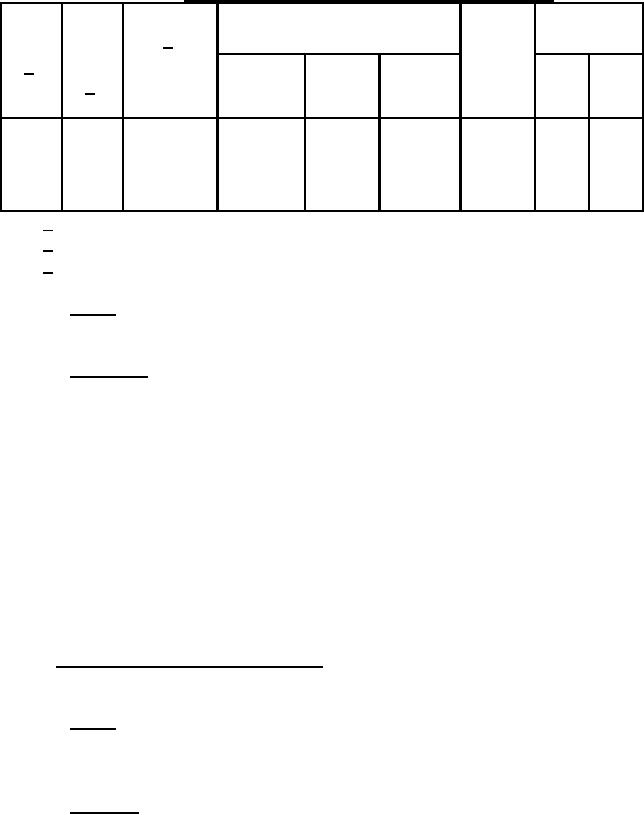
TABLE III. Regulator endurance time schedule and conditions.
Cyclic load,
seconds
3/
Alternator resistive load
1/
System
Constant Cyclic
Total
Load
Time,
2/
voltage,
current, current, current, cycles,
hours
RPM
volts
A
A
A
minutes On
Off
2400 26.5 0.75
1.5
320
330
650
90
3
57
5120 26.5 0.75
7.5
320
330
650
450
3
57
3520 26.5 0.75
14.5
320
330
650
870
3
57
8000 26.5 0.75
0.5
650
0
650
30
--
--
1/
24 hours per cycle.
2/
Alternator.
System voltage shall be applied at +225 degrees Fahrenheit (F).
3/
3.5.4 Safety. The regulator case shall not pose an electrical hazard due to improper
grounding (see 4.4.3.4).
3.5.5 Nameplate. A permanently and legibly marked nameplate shall be conspicuously
attached to the regulator housing and shall contain, as a minimum, the following information (see
4.4.3.5):
a.
Regulator, solid state.
b.
28 volts dc.
c.
Army part number.
d.
National stock number.
Manufacturer s identification (CAGE).
e.
Manufacturer s serial number.
f.
g.
Contract number.
h.
Date of manufacture.
i.
US.
3.6 Operating environment requirements. Each regulator shall operate under the
environmental conditions as specified in 3.6.1 through 3.6.6 (see 4.4.4).
3.6.1 Shock. The regulator shall withstand 40 gravity units (g) of sawtooth shock pulses
in accordance with figure 6 for an 18 3 millisecond (ms) duration in each of the major mutually
perpendicular axes without damage (see 4.4.4.1).
3.6.2 Vibration. The regulator shall withstand a maximum input vibration as specified in
figures 7 and 8 in each of three mutually perpendicular axes without damage (see 4.4.4.2).
6
For Parts Inquires call Parts Hangar, Inc (727) 493-0744
© Copyright 2015 Integrated Publishing, Inc.
A Service Disabled Veteran Owned Small Business