MIL-DTL-13791G
3.4 Design and construction. Distributors shall conform to applicable drawings and standards for
type and class (see 1.2). Authorized repair parts will conform to the form and dimensions specified on the
drawings specified in table I (see 3.3.1, 4.10.1, 4.10.2 and 6.2).
3.4.1 Interchangeability. All distributor assemblies and authorized repair parts shall be physically
and functionally interchangeable with all other products of the same part number (see 4.10.1 and 4.10.2).
3.4.2 Housing. Distributor housing shall be so constructed as to be electrically continuous
(see 4.10.2).
3.4.2.1 Coil-to-distributor lead. When specified (see 6.2), provision shall be made to permit
connection to coil-to-distributor lead for testing purposes (see 4.10.1 and 4.10.2).
3.4.3 Timing: initial setting. Timing of distributor shall be accomplished by rotation of the complete
distributor assembly in its mounting (see 4.10.2).
3.4.3.1 Advance and retard. Spark advance mechanism will be centrifugal. The centrifugal spark
advance mechanisms must continuously adjust timing of voltage output at the spark gap in conformance
to the advance curve specified on applicable drawings or military standards (MS) (see 4.10.1 and 4.10.2).
3.4.4 Drive arrangement. Distributor shaft speed will be one-half crankshaft speed. Drive end of the
shaft will be designed so that mating parts will not be assembled 180 degrees (º) out of line (see 4.10.2).
3.4.5 Ventilation. Provision will be made for ventilation as specified on applicable drawing or MS
sheet (see 4.10.1 and 4.10.2).
3.4.6 Lubrication. The breaker cam follower will be designed so that no additional lubrication will be
required when operation time is less than 100 hours. The rotor shaft bearing must be designed so that no
additional lubrication will be required when operation time for class 1 distributor is less than 600 hours
and when operation of class 2 distributor is less than 1500 hours (see 4.10.2).
3.4.7 Threaded parts. Screw threads of the form, number per inch, and class specified on the
applicable drawing or MS sheet must be in accordance with FED-STD-H28/2 (see 4.10.1 and 4.10.2).
3.5 Performance.
3.5.1 Voltage output. The distributor will produce no less than minimum voltage output at each
output terminal under operating conditions specified in table llI. Variation of output voltage from output
terminal to output terminal will be no more than 10 percent (%). When operating, the distributor will
produce no less than 6000 V dc at output terminals. The distributor must then be operated for 3 hours at
300 revolutions per minute (rpm) and 3 hours at 1800 rpm. Thereafter, the distributor cap will be
examined and there will be no evidence of cap and rotor interference (see 4.10.3).
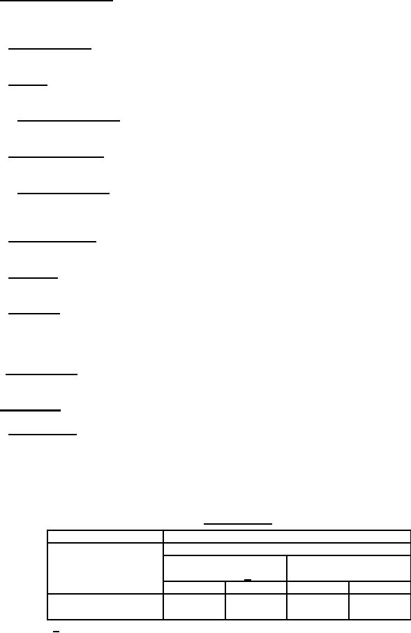
TABLE llI. Voltage output.
Output
Conditions
Voltage output, minimum kilovolts (kV)
Distributor shaft speed Ambient air temperature Ambient air temperature
200 10ºF
77 15ºF 1/
(rpm)
18 V input 30 V input 18 V input 30 V input
300 10
14 kV
17 kV
10 kV
15 kV
1800 25
12 kV
17 kV
10 kV
14 kV
1/ °F = degrees Fahrenheit
6
For Parts Inquires call Parts Hangar, Inc (727) 493-0744
© Copyright 2015 Integrated Publishing, Inc.
A Service Disabled Veteran Owned Small Business