MIL-PRF-62061D
IG
EG
T1
B +
A
S1
S2
S3
BLOWER
GENERATOR
LOAD TM
BANK
BATTERIES
A
B-
T2
EF
TM
HYDRAULIC TURRET MOTOR
IF
GEN FRAME TEMP
T1
T2
GEN INLET AIR TEMP
GEN OUTPUT AMPERES
IG
EG
GEN VOLTS
IF
GEN FIELD AMPERES
EF
GEN FIELD VOLTS
COMPONENT TERMINAL
DESIGNATIONS
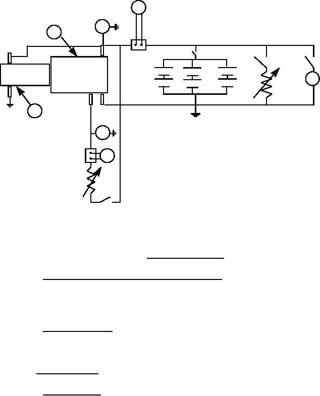
FIGURE 3. Generator test circuit.
4.5.2.1 Output, performance checkpoint (heat stabilized). To determine conformance to
3.3.2.1, the generator shall be subjected to the same test procedure as specified in 4.5.2 except
that the output shall be determined at only the one performance checkpoint indicated on the
performance curve on figure 1.
4.5.2.2 Speeds and current. To determine conformance to 3.3.2.2, the armature shall
rotate freely except for brush drag. Each generator shall be tested at room temperature,
77 ±15 F and shall not exceed the maximum speeds specified in 3.3.2.2.
4.5.3 Interpole voltage.
4.5.3.1 Instrumentation. To determine conformance to 3.3.3, a standard movement
meter shall be used for voltage and current measurements during tests. A standard thermometer
shall be used for temperature measurements of generator cooling fan intake air. Thermometer
shall be located in line with fan centerline at a distance of 36 in. ±6 in. from fan. Thermometer
shall be shielded from any hot surface radiations that may be present. The generator inlet
cooling air shall be ducted to simulate the ducting configuration of the generator installation of
the M60A1 vehicle (see 3.3.3).
11
For Parts Inquires call Parts Hangar, Inc (727) 493-0744
© Copyright 2015 Integrated Publishing, Inc.
A Service Disabled Veteran Owned Small Business